
The bilge pump is running, but no water is coming out. Should it be replaced? Motor noise alone does not establish that the system is moving water. With a common submersible centrifugal bilge pump, water must reach the impeller, air needs an escape path, and the pump must overcome the resistance of the installed discharge system. This article focuses on that pump type; a self-priming diaphragm dry-bilge pump works differently.
Why a spinning impeller may not move water
A centrifugal pump transfers energy from a rotating impeller to water. If an air pocket prevents water from reaching the impeller properly, the motor can keep running without establishing the expected discharge. Submerging the outside of the pump does not, by itself, prove that the impeller chamber has vented.
Xylem’s Rule demonstration shows one possible mechanism: after shutdown, water stays in a low section of discharge hose and traps air between that water and the pump. On restart, the non-self-priming centrifugal pump may be unable to clear the trapped air. See the manufacturer’s demonstration and accompanying transcript.
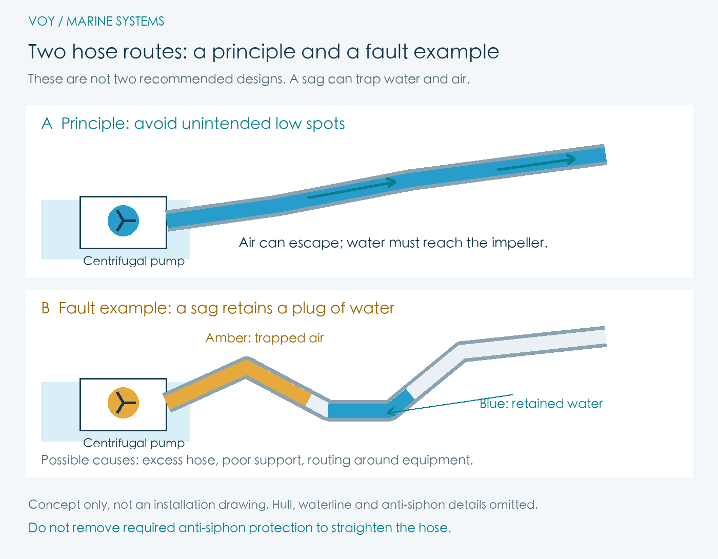
Why would a boat have the lower hose route?
Route A illustrates the aim of avoiding unnecessary low spots; route B illustrates a possible installation fault. They are not two alternative recommended designs. The low route is not intended to improve drainage or stop seawater coming back in.
In a real engine room, the pump may sit deep in a sump while the hull outlet is higher and further away. The hose has to pass around equipment, partitions and access spaces. Extra hose may be left during replacement, a support may be missing, or a flexible span may sag over time. Any of these can create a local valley after an initial rise. These are general engineering possibilities, rather than findings about a particular vessel.
How the valley can lead to an airlock
- During pumping: water can pass through a hose that is already filled, so the installation may appear to work.
- After shutdown: some water drains back towards the bilge, while some stays in the valley. Air occupies the drained section.
- At the next start: depending on water level and geometry, the retained water can block the air’s escape route from the impeller chamber.
- While the motor runs: if the impeller is mostly in air, it may not develop enough useful pressure to clear the water trap and establish flow.
This explains why a pump can work on one cycle and fail to discharge on another. It does not mean every sag always causes an airlock. Pump design, venting, start level, retained-water position and vessel attitude all matter. A sag is a diagnostic clue, rather than a complete diagnosis.
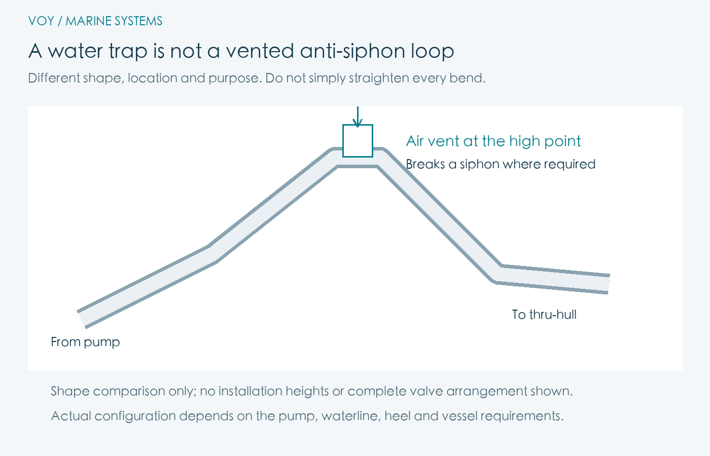
A low water trap is different from an anti-siphon high loop
A low valley retains water by gravity and can obstruct venting. A properly arranged vented high loop serves a different purpose: admitting air to interrupt a siphon where that protection is required. An ordinary raised bend is not automatically a vented anti-siphon device. Do not cut out a required high loop simply to make the hose look straight.
The Rule Standard manual sets out discharge arrangements according to the outlet’s relationship to the heeled waterline. It also states that a check valve is not a substitute for anti-siphon protection. Actual routing must be checked against the relevant pump manual and vessel installation. The drawings here omit the hull, waterline, dimensions and complete valve arrangement.
14-second animation: why a running pump may not discharge
Open video in a new window ↗
The sequence illustrates one airlock mechanism. It does not prescribe an installation layout. After correcting a fault, verify actual discharge and automatic operation while retaining the vessel’s necessary anti-siphon protection.
Separate four symptoms before replacing parts
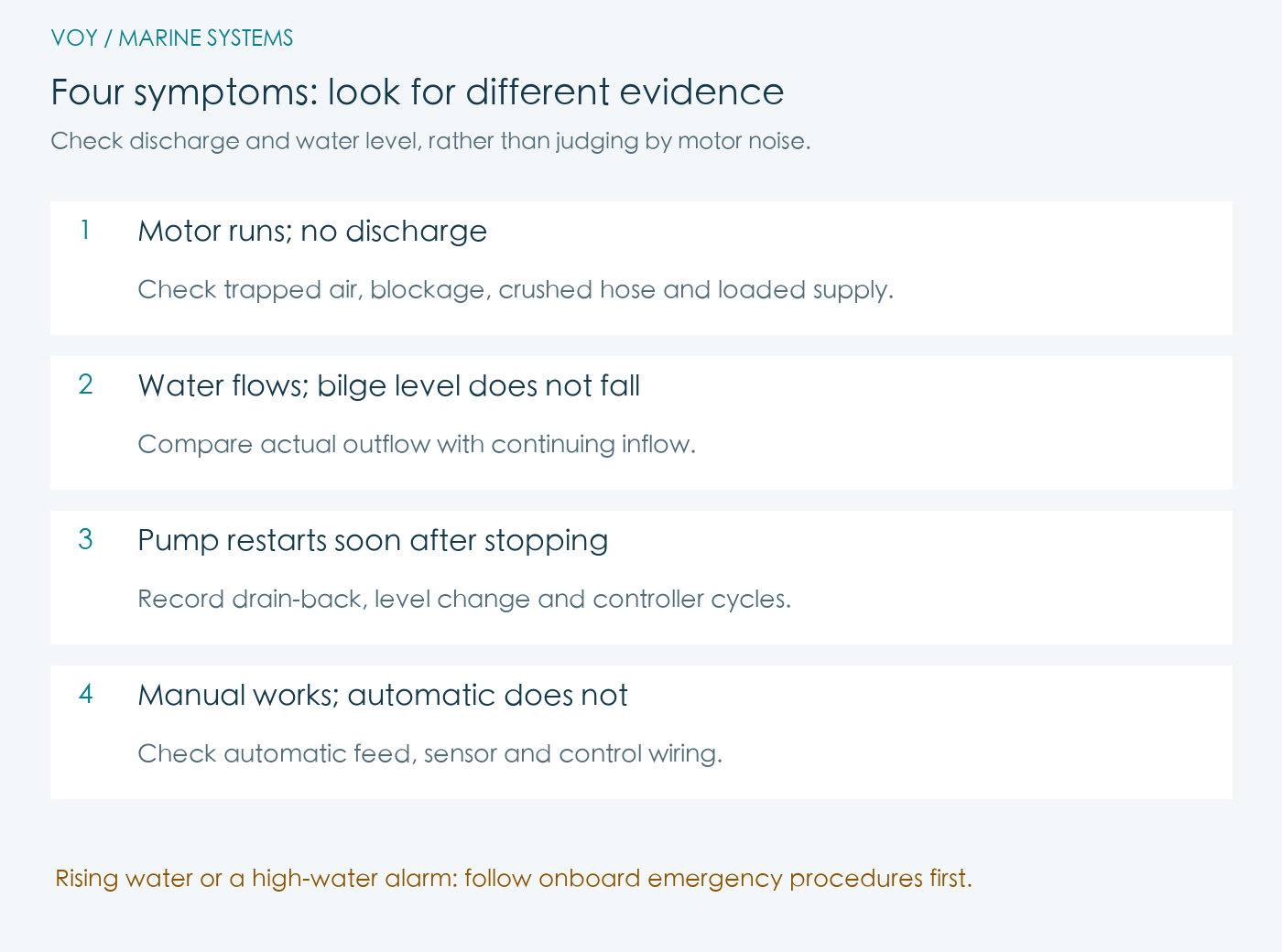
1. Motor runs, but there is no discharge
Confirm that you are watching the correct outlet and record the water level when the pump starts. With power isolated before touching the pump, inspect accessible intake screens, the impeller and hose for debris, crushing, sharp bends and unintended low spots. An air-filled chamber is one possibility; a blocked intake or damaged impeller is another.
Have a competent marine electrician check voltage at the operating pump, current and circuit voltage drop where needed. An unloaded reading at the battery does not establish the supply available under load. The Rule DB412 manual also identifies running motor-terminal voltage as a performance factor, but its numerical limits and installation details must not be transferred to unrelated pump models.
2. Water comes out, but the bilge level does not fall
Compare actual outflow with continuing inflow. A working pump cannot lower the water level if water enters as fast as, or faster than, it leaves. Investigate the ingress; fitting a larger pump does not repair a leak.
The GPH number on a pump is not a guarantee of installed output. Lift, hose length, bends, internal roughness and restrictive fittings all affect delivery. The Rule Standard 1500–4000 manual provides performance at different heads and explains plumbing losses. Use the applicable model’s data under the relevant conditions.
3. The pump restarts shortly after stopping
Water draining back from the discharge hose may lift the switch again. Continuing ingress, an obstructed float or an electronic controller’s programmed cycle can also cause repeated operation. Record whether shutdown, visible drain-back and restart follow one another before replacing the switch.
Some Rule-Mate configurations use electronic sensing and can enter a protective checking mode when the sensing area is contaminated, as described in the manufacturer’s technical explanation. Identify the exact model and control logic before interpreting brief starts as a fault. This behaviour is not universal to all Rule pumps.
4. Manual pumping works, but automatic operation does not
A successful manual test establishes only that the pump and discharge path worked at that time. It does not validate the automatic supply, float switch, sensor or control wiring. Check these against the vessel’s wiring diagram, and verify manual operation, automatic operation and the high-water alarm separately. Do not disable automatic protection simply to stop nuisance cycling.
How much water can drain back?
This is a geometry example, not a measurement from a vessel. A full circular hose with a 25 mm internal diameter and a length of 3 m contains:
V = π × (0.025 m ÷ 2)² × 3 m ≈ 0.00147 m³ = 1.47 L
That is its full internal volume, not a claim that 1.47 L returns on every cycle. Drain-back depends on routing, retained water and other components. If all that volume returned to an assumed effective sump area of 0.10 m², the idealised level rise would be 0.00147 ÷ 0.10 = 0.0147 m, or 14.7 mm. Real bilges have slopes, frames and connected spaces, so the effective area must be assessed on board.
Whether the pump restarts also depends on the difference between its switch-on and switch-off levels. This is why identical hoses can produce different cycling behaviour in a narrow sump and a broad bilge.
Correct the routing, clear a vent, or replace the pump?
Evidence of retained water: inspect hose support and routing against the manufacturer’s instructions, then retest. Review the hull outlet and anti-siphon arrangement together; do not assume a larger pump will compensate for a poor route.
A model-specific venting issue: the Rule LoPro explanation identifies a blocked factory vent in the discharge port as a possible cause of slow priming. Confirm the exact equipment and follow its instructions. This is not general advice to drill holes or raise the activation level on every bilge pump.
Considering a check valve: consult the exact pump and fitting guidance. LoPro guidance restricts combining its check valve with its 90-degree discharge fitting because of back pressure. A check valve, vented loop and seacock have different functions and cannot simply replace one another.
Replacing the pump: establish evidence of damage, unsuitable specification or failure to recover after appropriate cleaning. Compare head, hose size, electrical load, protection, mounting space and service access. Keep before-and-after discharge tests under comparable conditions.
Record discharge, automatic operation and the alarm
Keep the model, hose-route photographs, start and stop levels, manual and automatic test results, observable outlet flow and high-water alarm results. Repeat system checks after changing a hose, fitting or sensor. Maintain suitable alternative pumping and supervision while equipment is being serviced.
If bilge water contains oil or other contamination, do not discharge it overboard merely to demonstrate a pump. Collection, disposal and discharge permissions require separate checks against the applicable local rules. Manufacturer references here are technical information, not a complete Hong Kong compliance checklist.
For help coordinating maintenance or including bilge-pump and alarm checks in routine yacht management, contact Voy Yachting with the equipment model and observed symptoms.
Technical references
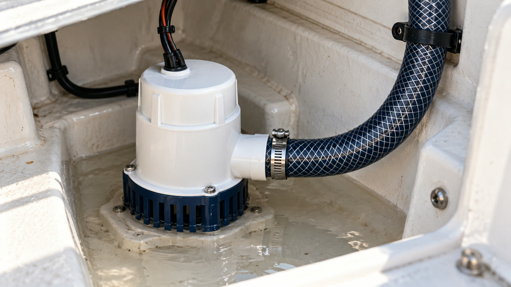
Technical references checked on 30 October 2026; editorial update on 31 October 2026. This is general technical education. The cover is a generated photographic-style illustration, not a photograph of a specific vessel or customer repair. The diagrams and animation explain concepts and are not installation drawings.
- Xylem / Rule: Explaining an Airlock in a Bilge Hose — accompanying technical transcript.
- Rule Standard Bilge Pump 1500–4000 manual, 950-0584A Rev D — performance and plumbing requirements for that series.
- Xylem: Rule LoPro troubleshooting — model-specific vent and fitting guidance.
- Xylem: Rule-Mate level-sense mode — electronic-control behaviour for applicable equipment.
- Rule Dry Bilge Pump DB412 manual — a different, diaphragm pump type; its specifications are not general centrifugal-pump limits.