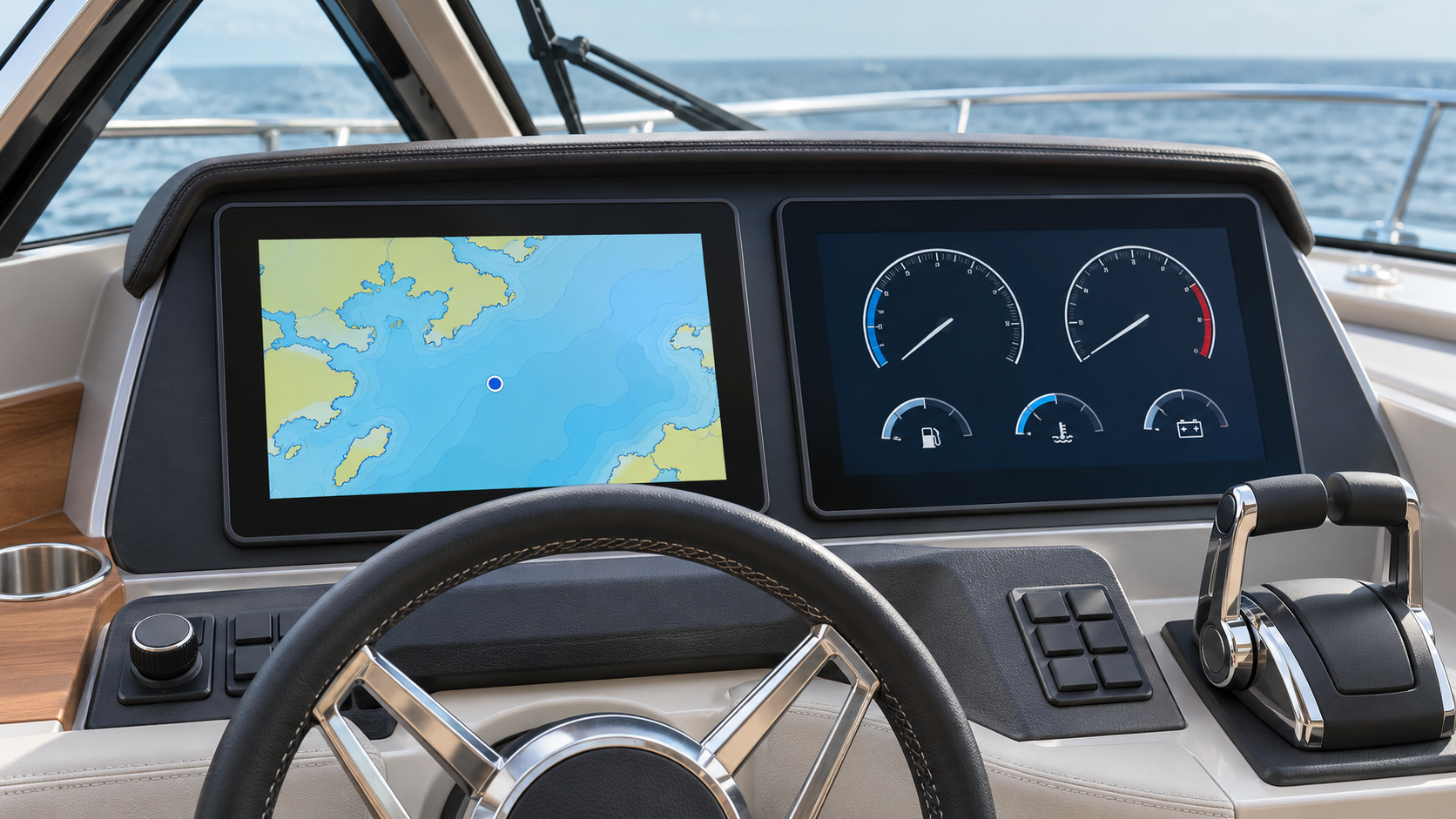

NMEA 2000 is a communications standard that allows compatible marine electronic instruments to exchange information. A simple owner’s requirement explains its purpose: the depth sensor is under the hull, but you want to see its reading at both the main helm and the flybridge. With a suitable source, network and displays, one source can serve both locations.
Start with the information available on the boat and where you want to see it. The connectors make more sense once you understand what they are connecting. Garmin’s definition of NMEA 2000.
1. What is it for? Bringing scattered information together
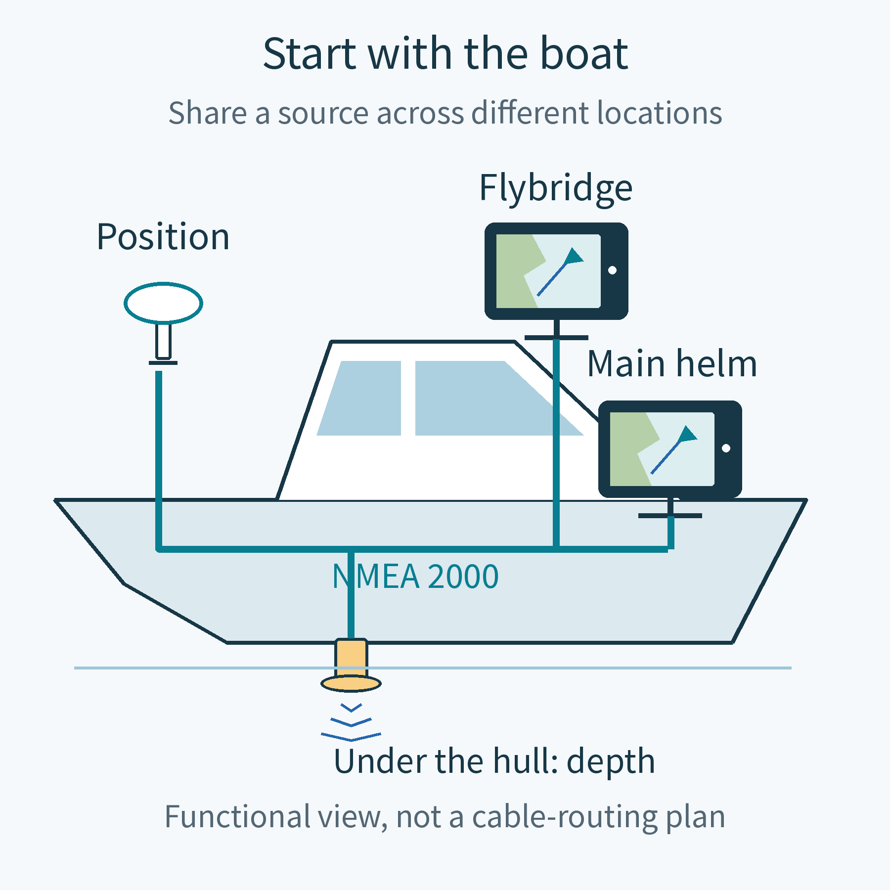
In the illustration, the position sensor is above deck, the depth source is under the hull, and the screens are at the helm stations. They do not need to sit together, but the person operating the boat needs access to their information. NMEA 2000 is one way for suitable equipment to communicate.
NMEA 2000 is not a particular brand of screen or a box that measures everything on the boat. It sets rules for connections and messages. The installed sensors, displays and cabling form the actual network. Compatible products can come from different manufacturers, but support for each required function still needs checking.
The practical benefit is using existing information where you need it. Adding a flybridge display may not require another depth source for the same purpose, provided the new screen can receive and use the existing source’s information. How sources determine displayed information.
2. How does it work? Follow one depth reading
Suppose a compatible depth source measures 8.2 metres. This is an illustrative value, not live navigation information. It forms a depth message and sends it onto a shared channel. Compatible main-helm and flybridge screens can each read that message and display the value. Manufacturer description of depth data.
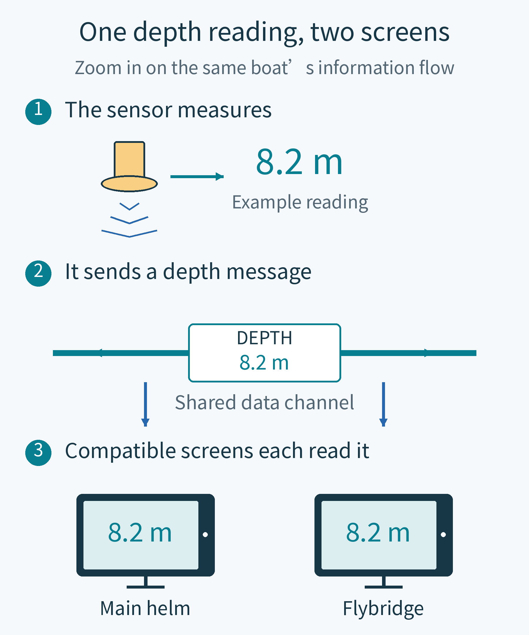
The shared item is information, not a copy of the first screen’s picture. The two screens can present the same source in different layouts. The second screen does not depend on the first forwarding a picture. The network can have multiple transmitting and receiving devices, without a central computer controlling all communication. NMEA’s description of the network.
The short video below uses position rather than depth to show the same principle: one source can serve two compatible displays. Moving dots illustrate information transfer, not electrical current or actual transmission speed.
Without a depth source, a networked screen cannot discover the depth by itself. A depth page on a display does not establish that a valid reading is available. Separating measurement from presentation makes the installation choices easier to understand.
3. Which instruments use it?
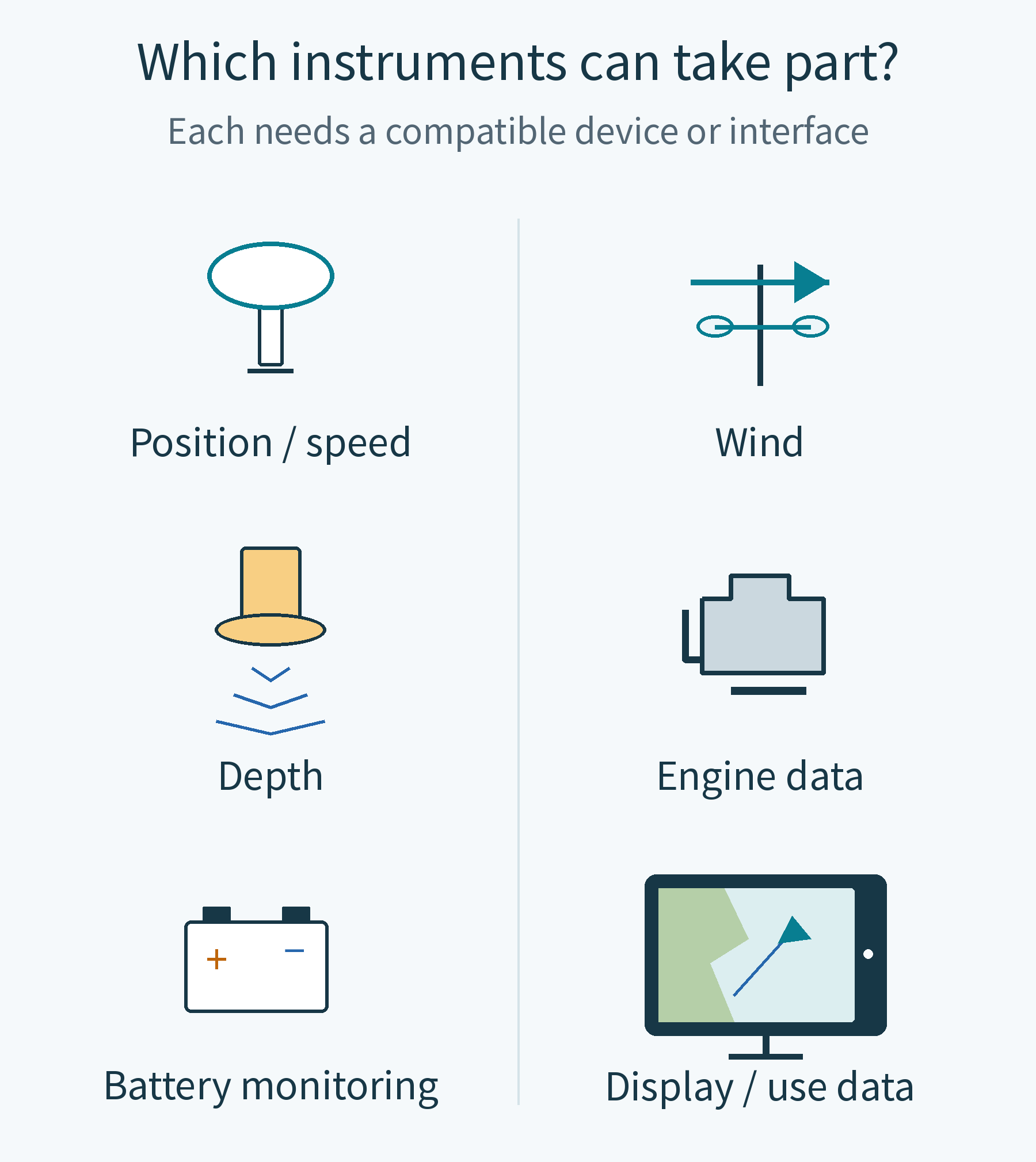
Start with the information you want, rather than a list of model numbers. The illustration shows equipment categories that can participate. A boat does not need every category, and equipment in a category is not automatically compatible.
| Information wanted | Typical source | Distinction to check |
|---|---|---|
| Position and speed over ground | A compatible position source | Some displays have built-in positioning; others use an external source. |
| Depth or wind | The relevant compatible sensor or interface | Each measurement needs an appropriate source, not just another screen. |
| Engine speed and other operating data | A supported engine interface | The engine and display combination may require specific interface equipment. |
| Battery status | Compatible monitoring equipment | Check both what the monitor measures and what the screen can display. |
These are data examples, not universal feature promises. The support table for specified Garmin GPSMAP models lists position, depth, wind, engine and battery data. Humminbird’s engine compatibility guidance shows why engine and display combinations may need different interfaces.
Radar imagery is a separate issue. A chartplotter displaying radar does not mean that the radar picture travels through NMEA 2000. Garmin, for example, specifies its marine-network connection for radar and states that the radar feature is not shared over NMEA 2000. Garmin radar connection guidance.
4. Now look inside: how is it installed?
Take the boat’s connections out of their physical locations and look at them together. This typical linear arrangement has instruments above a shared channel, components at the two ends, and a network power connection. See the whole arrangement before learning the part names.
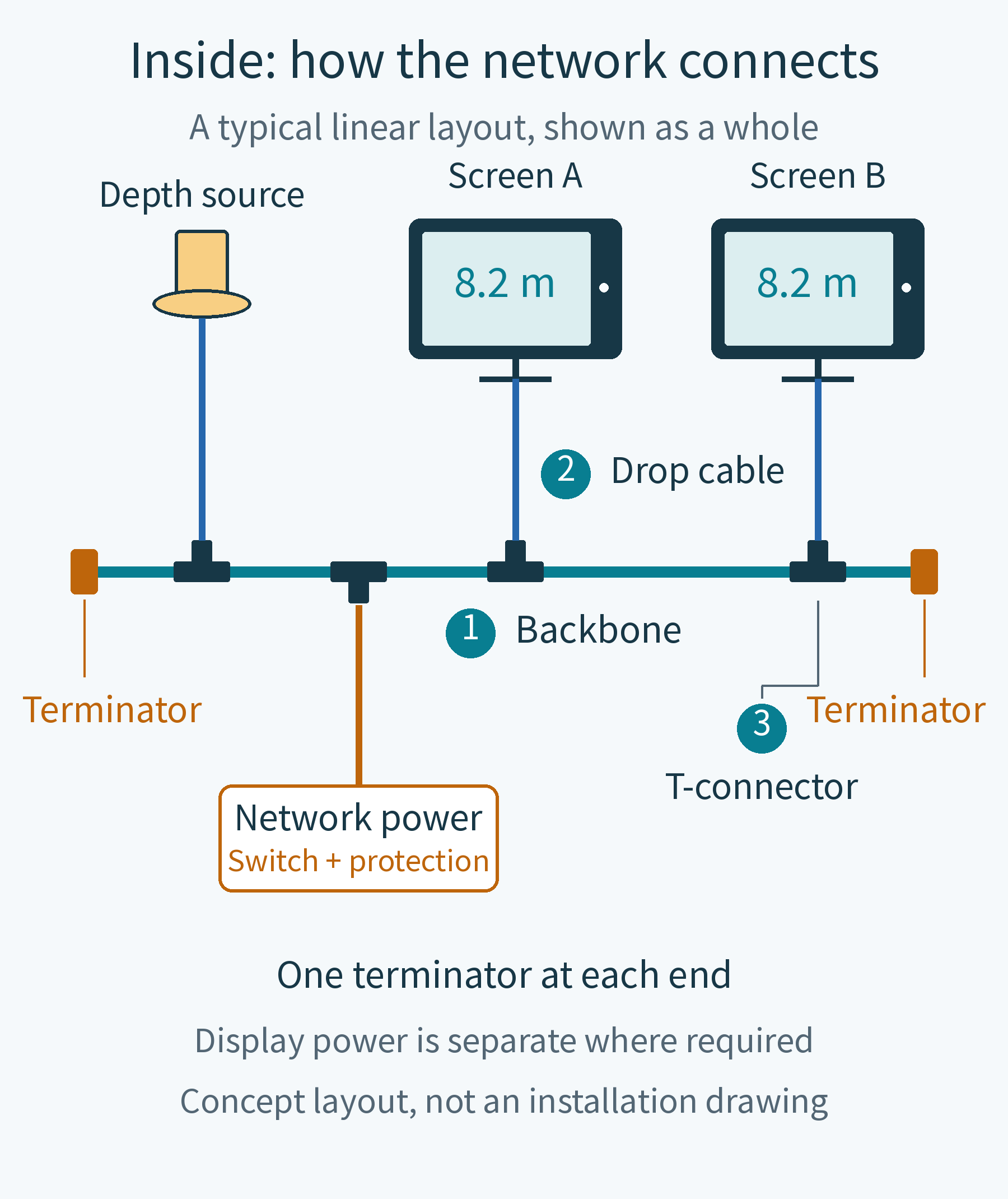
① The backbone is the shared horizontal channel. Suitable cables and connectors carry it through the areas it needs to serve. The straight line in the drawing describes the connection relationship; it does not require every cable on the boat to run in a geometrically straight line.
② A drop cable connects an individual device; ③ a T-connector provides the junction. In the conventional arrangement, the T’s sides continue the backbone and its branch connects the device. This explains why simply daisy-chaining screens in an arbitrary arrangement is not equivalent. Garmin’s linear-backbone guidance.
The orange components at the ends are terminators. They provide the required electrical termination for communication to work properly. They are not power supplies or an extra accessory for every instrument. This typical arrangement has one at each end; adding a device still requires the correct two endpoints. Termination guidance.
The remaining orange connection supplies the network. It belongs in the installation picture because the network needs suitable power. Some small devices draw power from it, while a chartplotter still requires its own supply as specified in its manual. The Garmin guidance used here specifies switched 12 V DC; a boat’s 24 V supply must not be connected directly. The installer checks supply location, protection, lengths and load for the actual equipment. Power requirements.
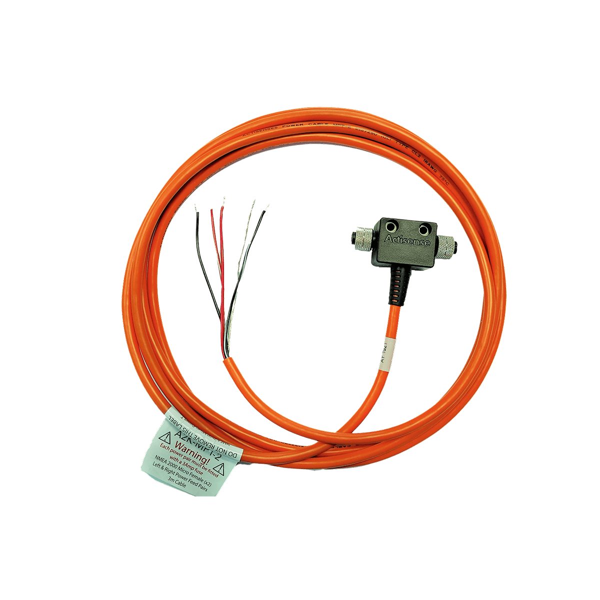
The A2K-MPT-2 introduces power into the network. It is neither a position sensor nor a data-format converter. Recognising its job in the complete arrangement makes the physical product easier to understand.
5. Which approach fits my boat?
An existing network: identify the missing information
Suppose you already have a position source, a network and a compatible screen, and now want depth. Start by identifying a suitable depth source and connection, and checking screen support. Replacing all the instruments is not the starting assumption. The illustration keeps the existing equipment and identifies the addition.
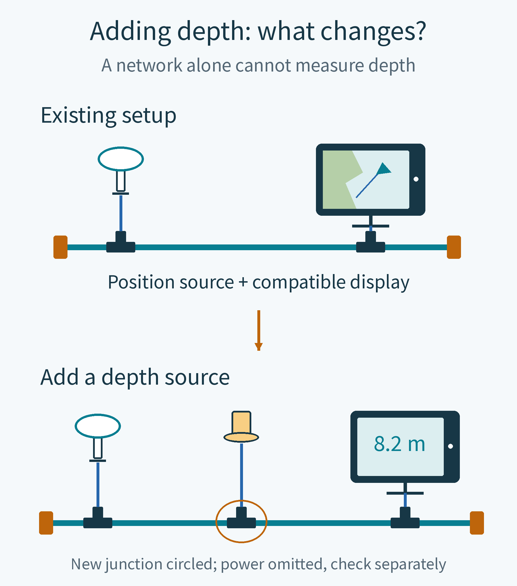
This is a planning example, not a guarantee of success by plugging something in. Check whether the existing network can be extended and whether lengths and power remain suitable. If the needed information is already available, the addition may instead be another display location.
A new installation: distributed cabling or a compact unit?
Equipment spread around the boat, or plans for later additions, may suit a backbone and drops planned around those locations. For equipment grouped more closely together, some products combine connection points and network components. Layout and expansion needs matter more than counting sockets.
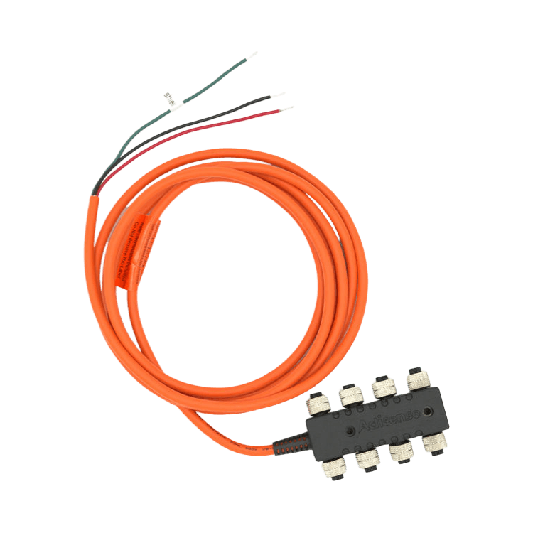
For example, the Actisense A2K-SBN-2 incorporates termination and a power cable. The manufacturer specifies up to eight devices and no further extension. That is this product’s limit, not an eight-device limit for every NMEA 2000 network. It must not be casually combined with the expandable linear concept illustrated earlier.
Keeping older instruments, or connecting a computer
An older instrument may use a different communications format, such as NMEA 0183. Changing the plug alone may not make its information usable. A gateway may be needed to convert supported messages between formats; its actual conversion list determines what is possible.
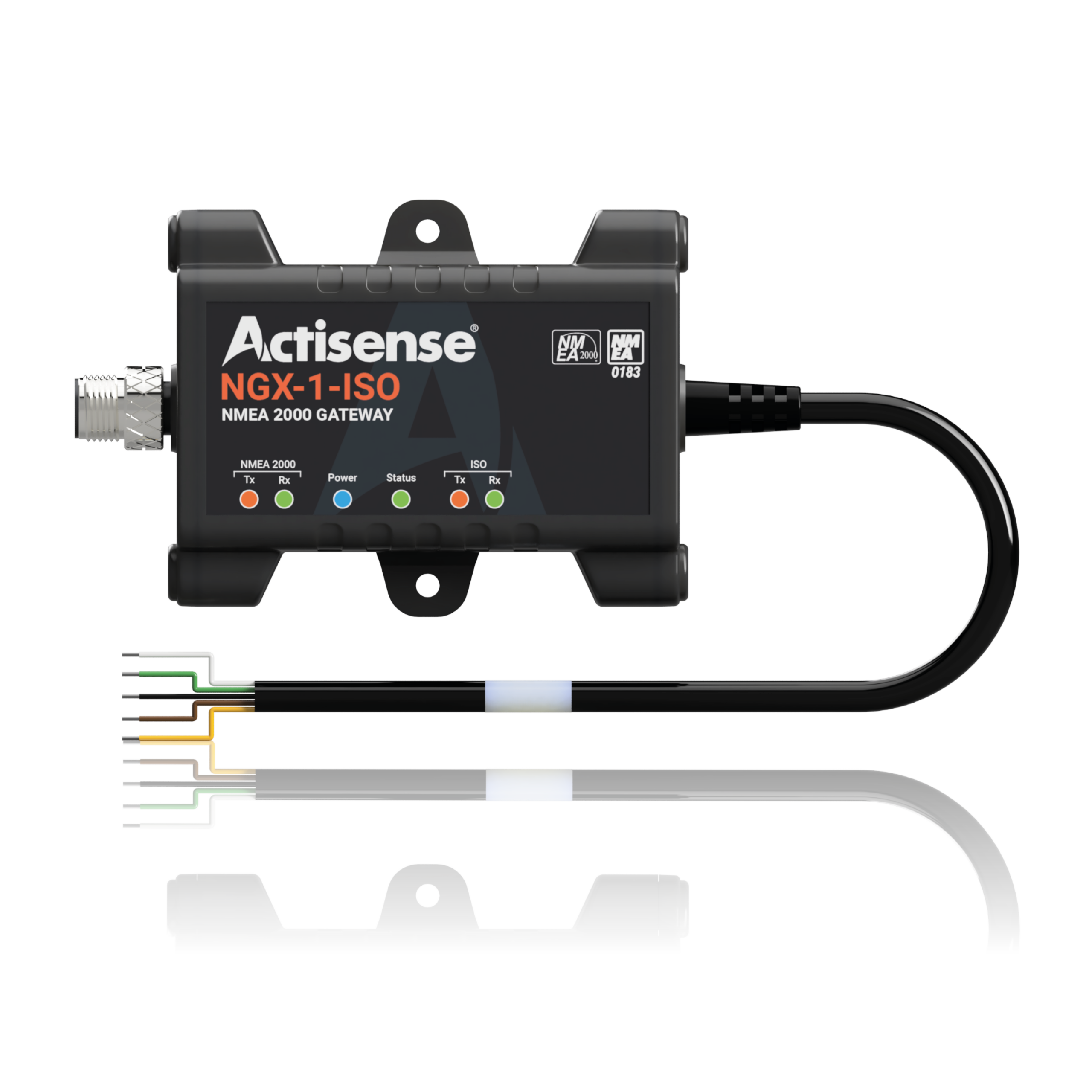
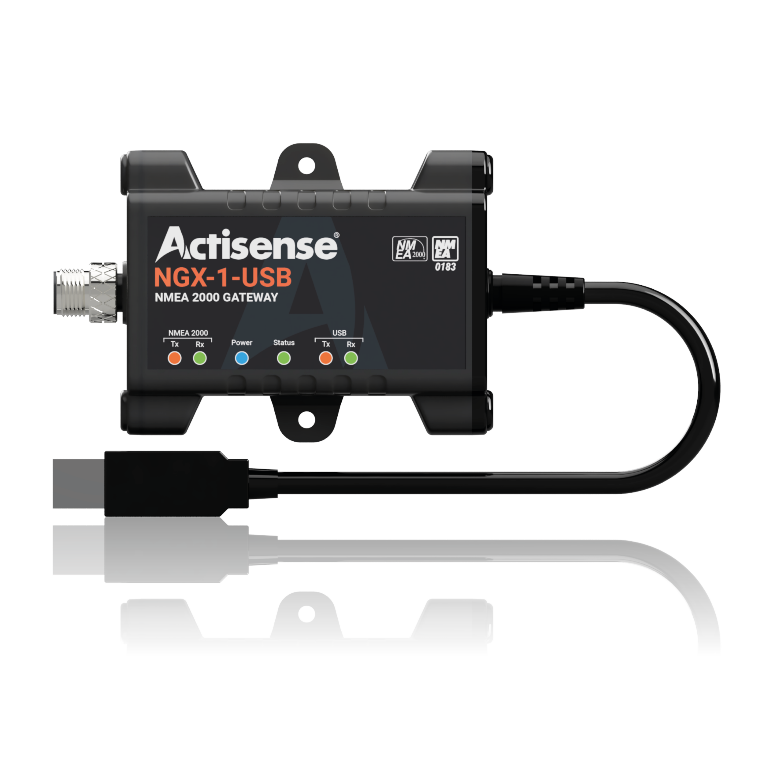
These NGX-1 versions have similar enclosures but different connections at the other end. First identify whether the requirement is an older instrument or a computer, then check the version, operating mode and required information. They are not compulsory parts of every new network.
6. Installation: define the result, then verify it
Write a concrete requirement: “Show the existing depth source on the flybridge.” List the source and display models, their locations and existing cabling. The installer can check data support, draw the network, measure distances and plan power and protection. After installation, select the source and verify each requested display. Each step then serves a purpose rather than becoming a shopping list of connectors. Garmin’s network-planning procedure.
Only at this stage do PGNs need introducing: they identify particular data items. Owners need not memorise them. Ask the installer to compare what the source transmits with what the display receives. At handover, request a demonstration of the required information, an explanation of its selected source, and an updated network drawing. Power changes, joining existing networks and integrating older instruments call for a technician familiar with the equipment.
For a yacht equipment update or repair, share your instrument models and the improvement you want with Voy to discuss appropriate maintenance coordination and follow-up support.